

Tools
Screwdrivers, drill, enclosure-safe drill bits, wire cutters, and a wire stripper.
Hardware assembly
Parts list and wiring diagrams
The goal is a clean, robust scale with no exposed wiring, suited to brewing environments.
Screwdrivers, drill, enclosure-safe drill bits, wire cutters, and a wire stripper.
Flexible wire, jack connectors, PG7 cable glands, and an RJ9 cable for the platform.
Work with power disconnected. Check 12V polarity before connecting the Dial or the valve.
After assembly, use the software guide to flash the firmware and calibrate the scale.

The M5Stack Dial provides the ESP32, Wi-Fi, round screen, and rotary encoder. It keeps wiring low and gives the brewer a physical interface that remains usable with wet hands.

The Unit Weight I2C converts the load-cell signal into data the Dial can read. Keep the wiring short and mechanically protected inside the enclosure.
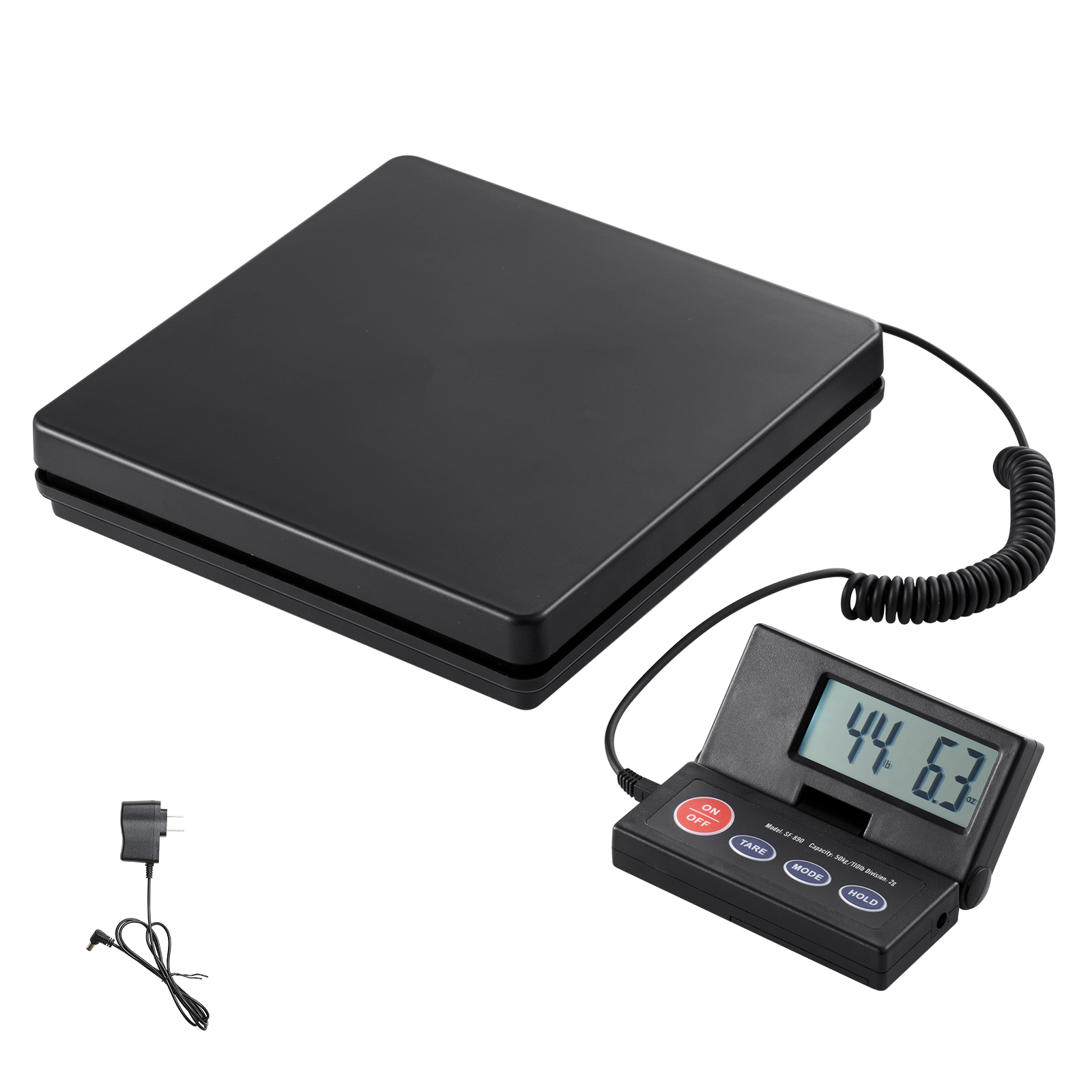
Compact, 25 kg max, with an RJ9 connector that makes integration easier.
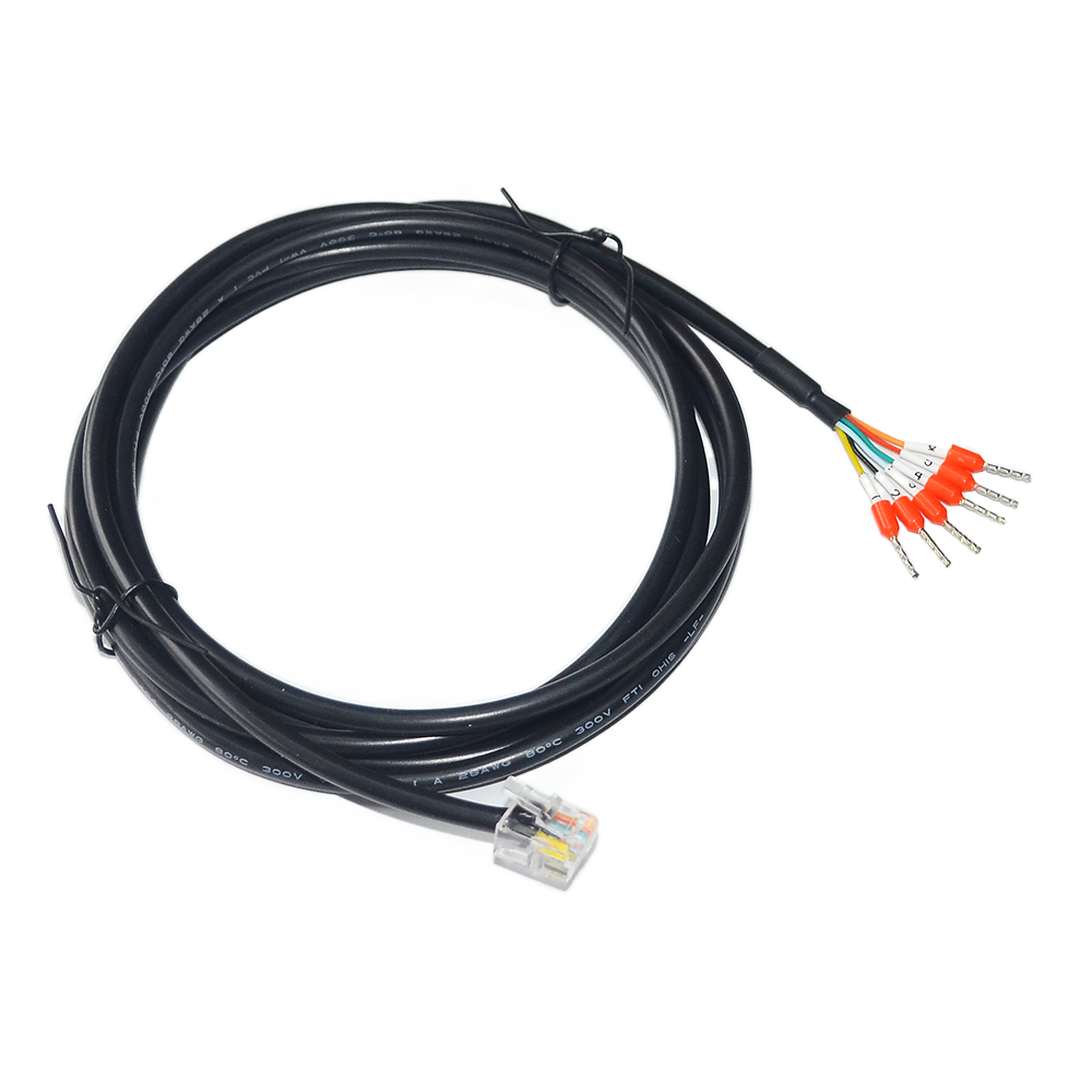
The RJ9 cable avoids hard-wiring the scale load cells. It provides a simple connection between the weighing platform and the Unit Weight I2C weight reader.
Add these parts only if you use keg filling.
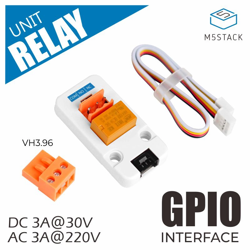
The Unit Relay switches the optional 12V solenoid valve for keg filling while keeping the control signal separate from the valve power path.
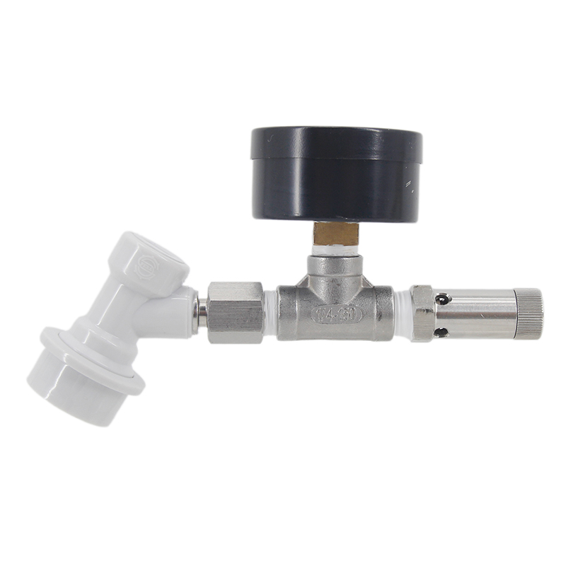
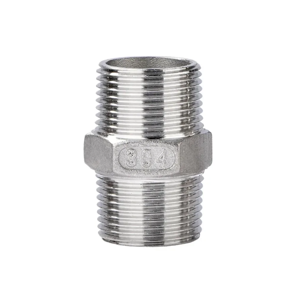
The spunding valve is only required for keg filling. It remains the mechanical pressure regulator while the scale controls the filling stop by weight.
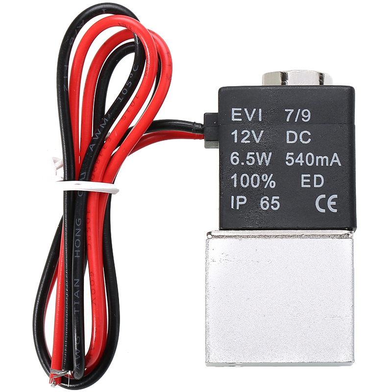
The normally closed solenoid valve gives the controller a safe way to stop filling. If power is lost, the gas path closes.

The enclosure gathers the electronics, protects the connections, and leaves only the useful cables exposed.
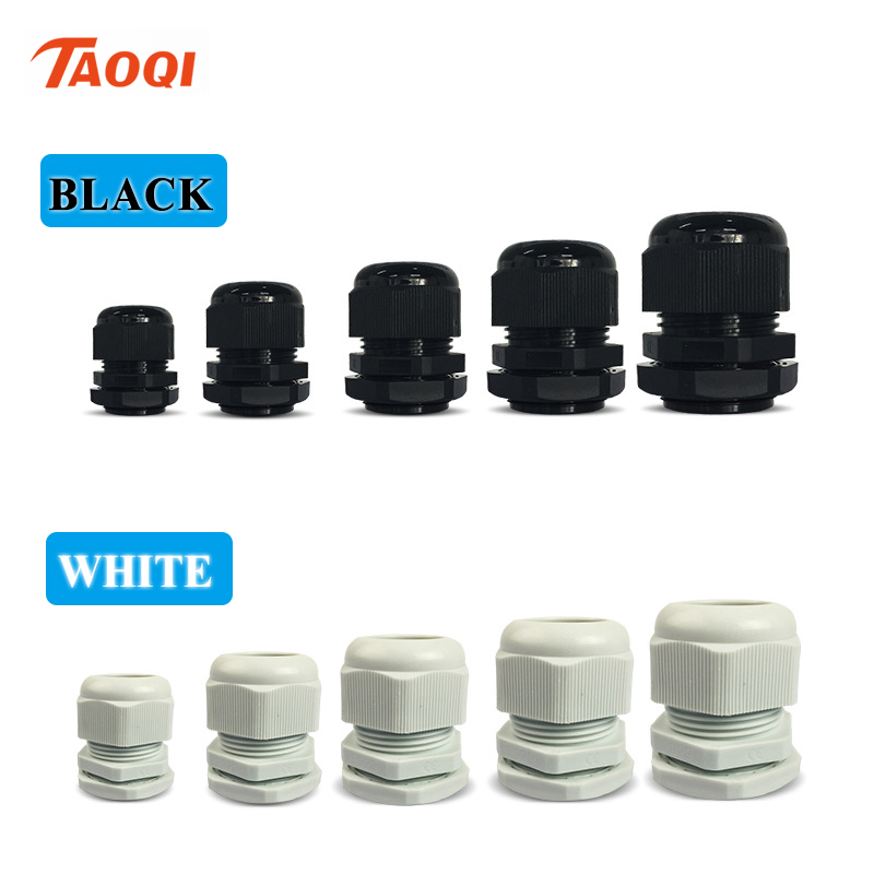
The cable gland provides strain relief for the RJ9 cable and helps keep splashes away from the electronics inside the enclosure.
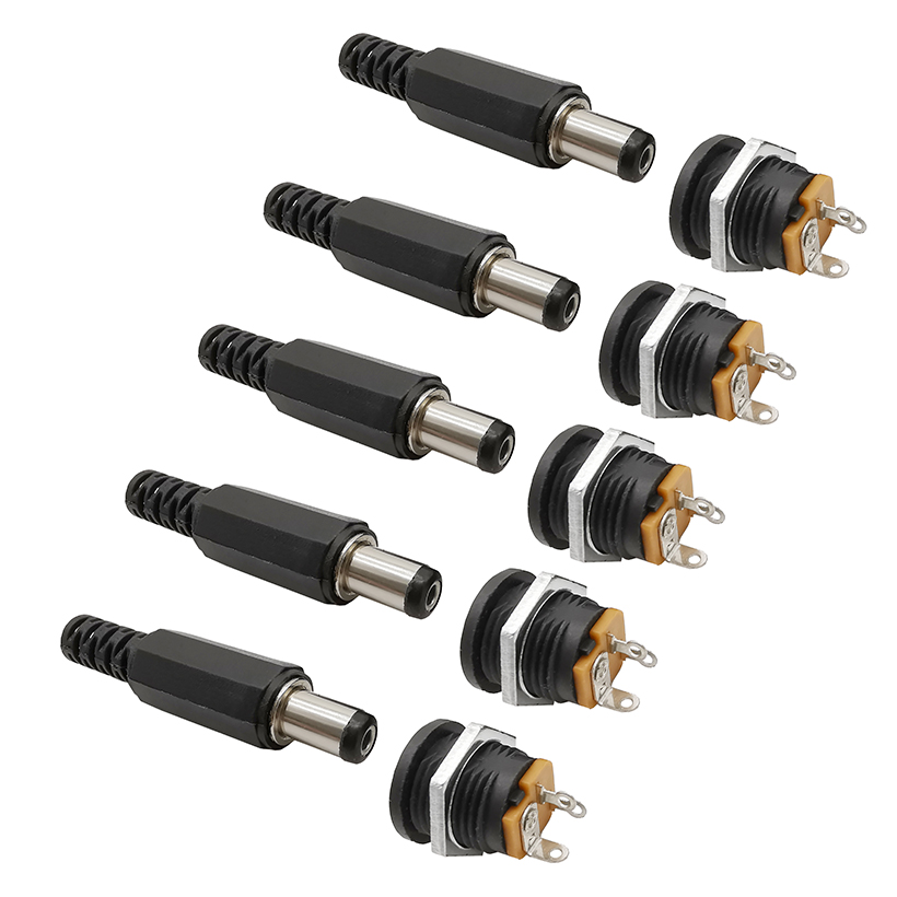
Jack connectors make power and optional valve wiring easier to disconnect for service or transport.
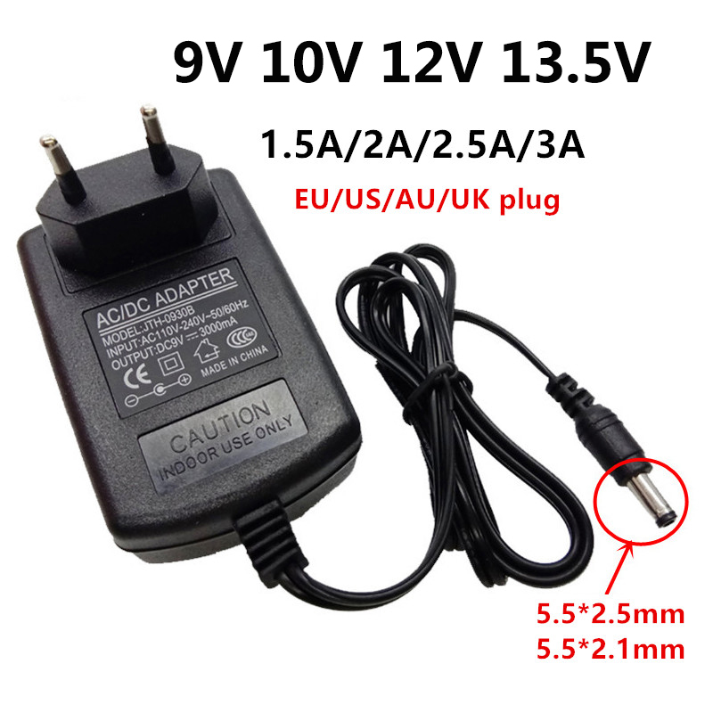
The 12V supply powers the build and shares the same voltage family as the solenoid valve used by the keg-filler option.
Position the M5Stack Dial so the screen and rotary encoder remain accessible. Then mark the required exits: 12V power, RJ9 scale cable, and valve output if the keg filler is installed.
Route the RJ9 cable into the enclosure through a cable gland, then connect it to the Unit Weight I2C weight reader.
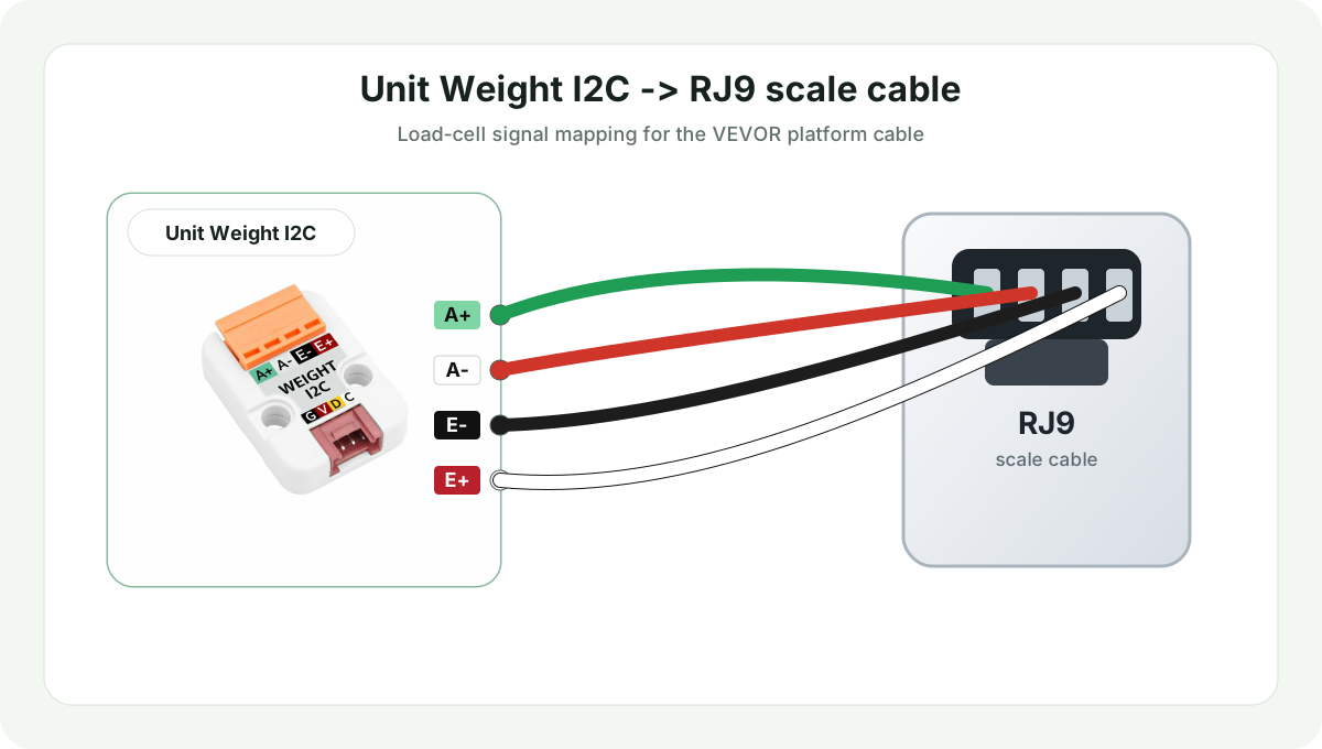
| Unit Weight Terminal | RJ9 Cable Wire |
|---|---|
A+ |
Green |
A- |
Red |
E- |
Black |
E+ |
White |
Connect the red Port A on the M5Stack Dial to the Unit Weight I2C Grove connector with the HY2.0-4P cable. This port provides the 5 V supply and the I2C bus required by the weight reader.
| Grove Wire | M5Stack Dial Port A | Unit Weight I2C |
|---|---|---|
| Black | GND |
GND |
| Red | 5V |
5V |
| Yellow | G13 / SDA |
SDA |
| White | G15 / SCL |
SCL |
0x26.
The 12V 3A power supply is the main input. Use jack connectors for a clean power entry, then distribute power to the modules that need it.
For keg filling, the relay drives the normally closed 12V solenoid valve. If the system loses power or restarts, the valve returns to the closed position and filling stops.
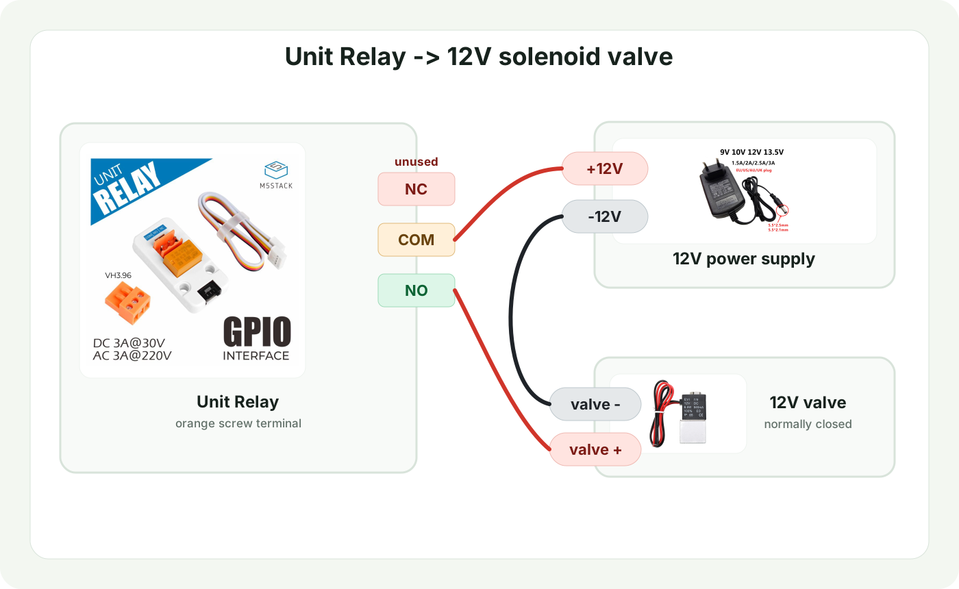
Connect the black Port B on the M5Stack Dial to the Unit Relay Grove connector with the HY2.0-4P cable. This port provides the 5 V supply and the relay control signal.
| Grove Wire | M5Stack Dial Port B | Unit Relay |
|---|---|---|
| Black | GND |
GND |
| Red | 5V |
5V |
| Yellow | G2 |
DIN |
| White | G1 |
NC |